Industrial Cartesian Robot Systems for Automated Positioning
When standard layouts do not fit the available installation space, our multi-axis linear modules can be configured around your machine drawing. This reduces the need to redesign the surrounding frame and makes mechanical integration more predictable.
- Review payload, travel length, and working envelope against your exact process.
- Select servo or stepper drives based on required positioning and cycle time.
- Confirm mounting-hole patterns and end-effector interfaces before production.
What Is a Cartesian Robot?
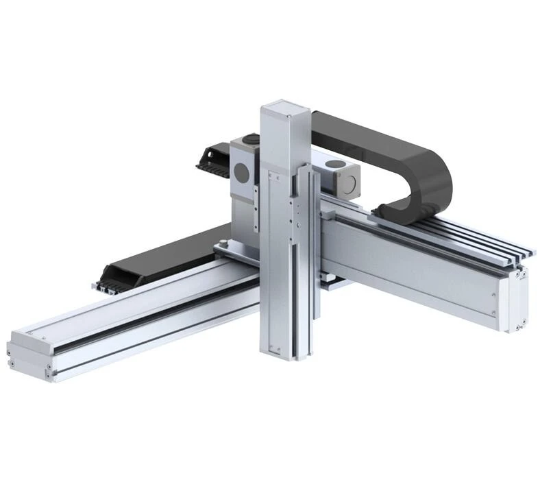
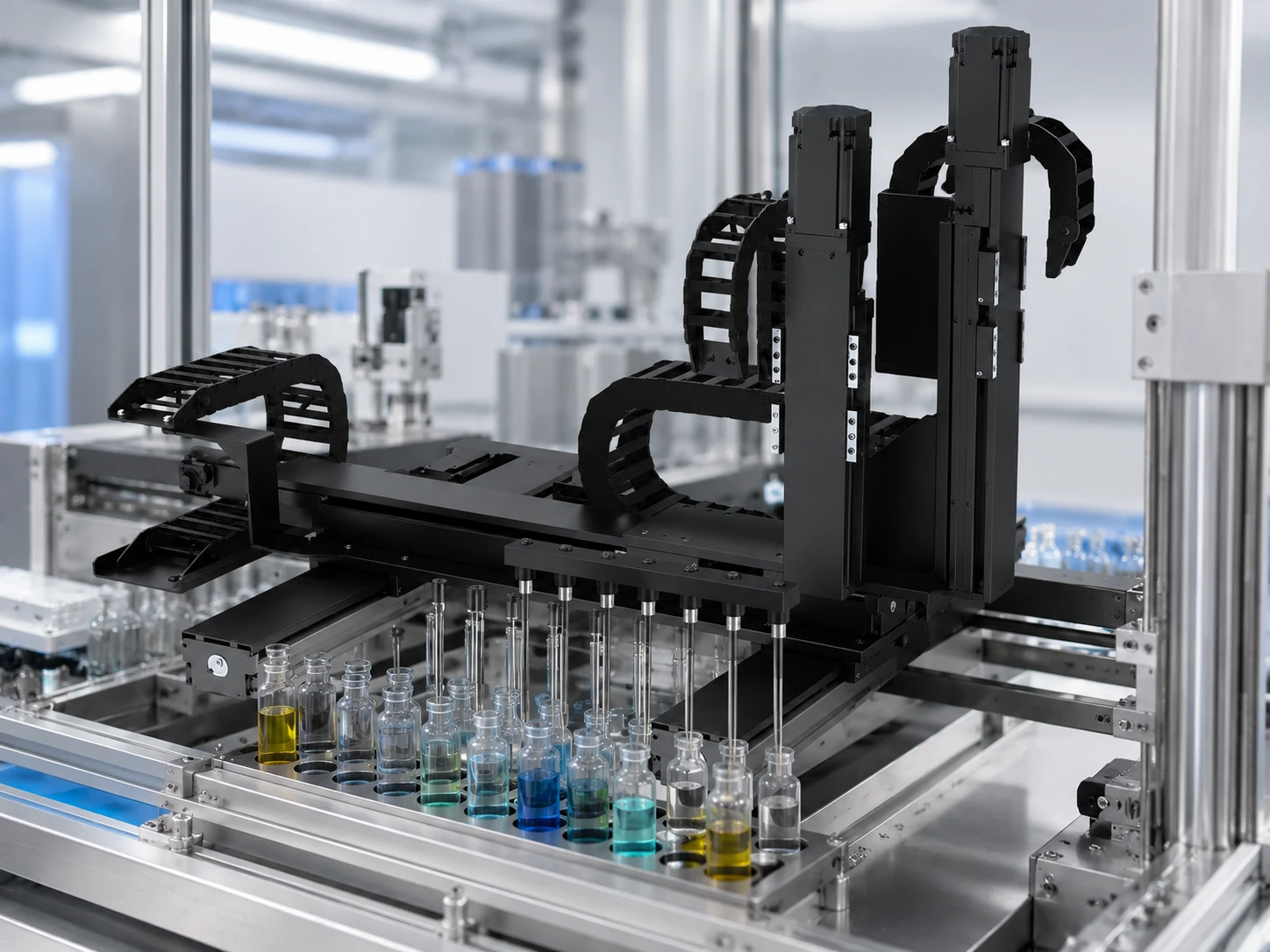
A Cartesian robot (also known as a linear robot, gantry robot, or XYZ robot) is an industrial automation system consisting of two or three linear axes arranged at right angles to each other. It operates within a distinct rectangular working envelope.
Because each axis (X, Y, and Z) controls one specific direction of motion independently, the system provides highly predictable, fixed-path automation. This structure allows engineers to configure the payload capacity and travel length individually for each axis, making it suitable for tasks ranging from small-scale component assembly to heavy overhead material handling.
Core Characteristics
- • Rectangular working envelope
- • Independent axis configuration
- • Scalable payload and travel customization
- • Predictable mechanical integration
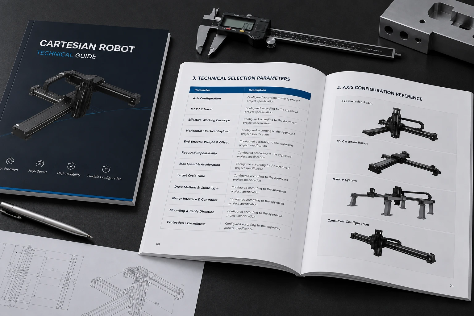
Cartesian Robot Configurations
Review the structural options based on your required working envelope, mounting direction, and payload condition.
1. Single-Axis Linear Module
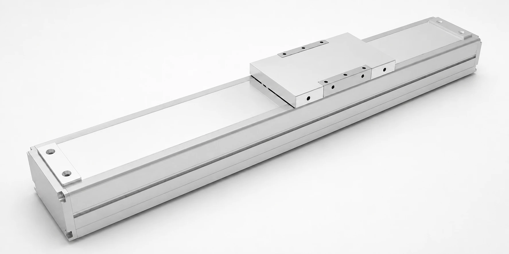
Structure: A standalone linear motion axis.
Application: Single-direction transfer or machine loading.
Constraint: The mounting base must meet specific flatness requirements to prevent guide rail binding over long travel.
Benefit: Simplifies point-to-point movement without requiring a multi-axis controller.
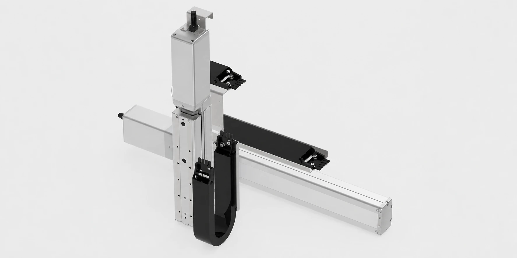
2. XY Two-Axis Cartesian Robot
Structure: Two axes mounted perpendicular to each other.
Application: Two-dimensional positioning, dispensing, or cutting.
Constraint: The lower axis must possess sufficient structural rigidity to support the weight and dynamic movement of the upper axis.
Benefit: Allows for continuous path control across a flat working envelope.
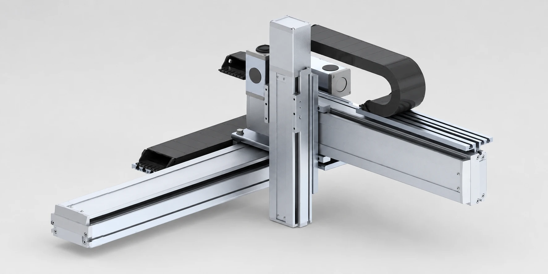
3. XYZ Three-Axis Cartesian Robot
Structure: Three independent axes providing full spatial movement.
Application: Three-axis pick and place, assembly, or palletizing.
Constraint: The vertical Z-axis payload holding requirements must account for braking and falling prevention during power loss.
Benefit: Offers a complete volumetric working space with predictable corner integration.
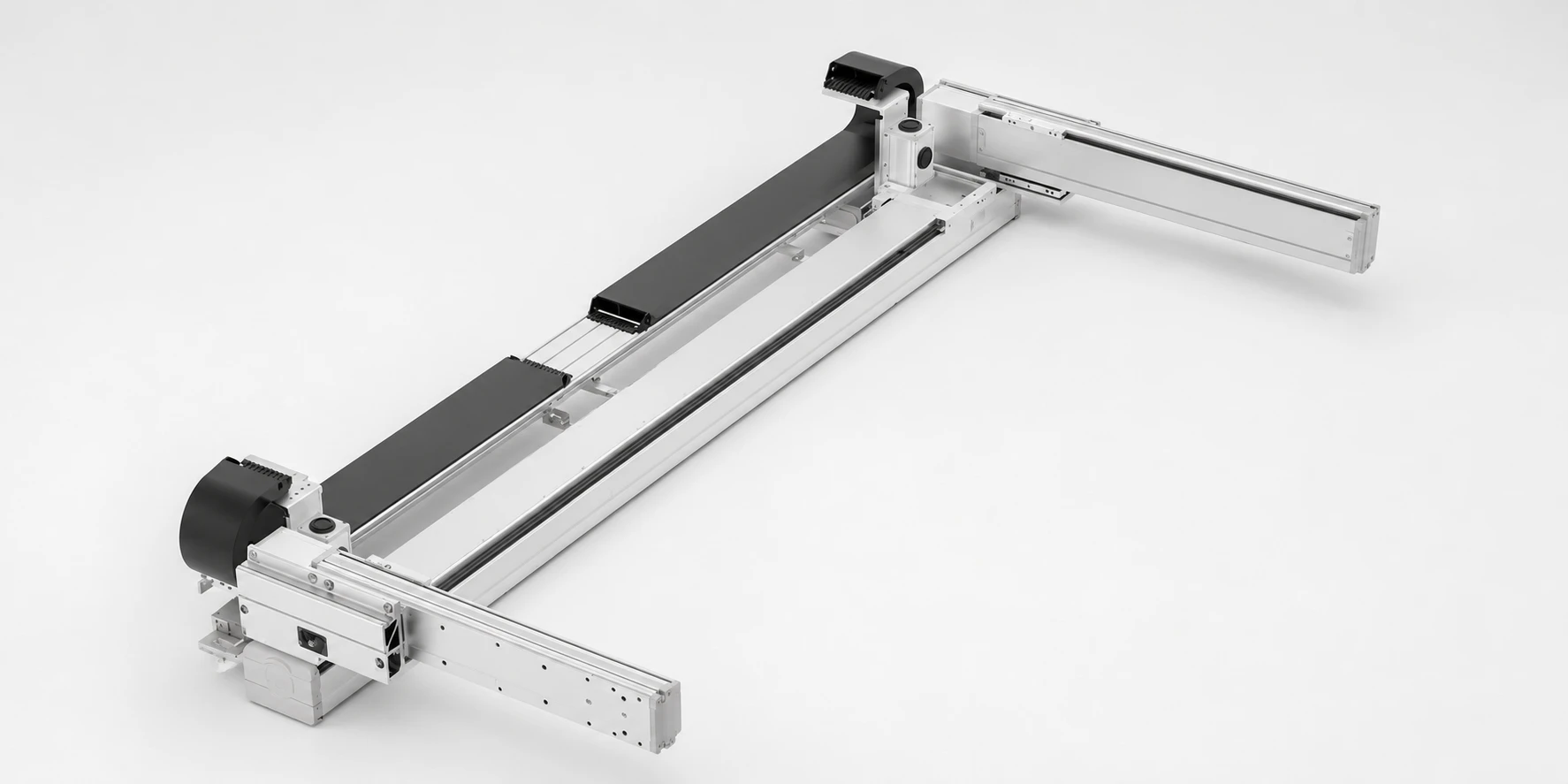
4. Gantry Cartesian Robot
Structure: A suspended X-axis beam supported by dual parallel base axes.
Application: Large-area overhead handling and heavy payload transfer.
Constraint: Requires dual-drive synchronization and strict parallel-axis alignment to prevent beam deformation.
Benefit: Keeps the central workspace entirely clear for large workpieces or conveyors.
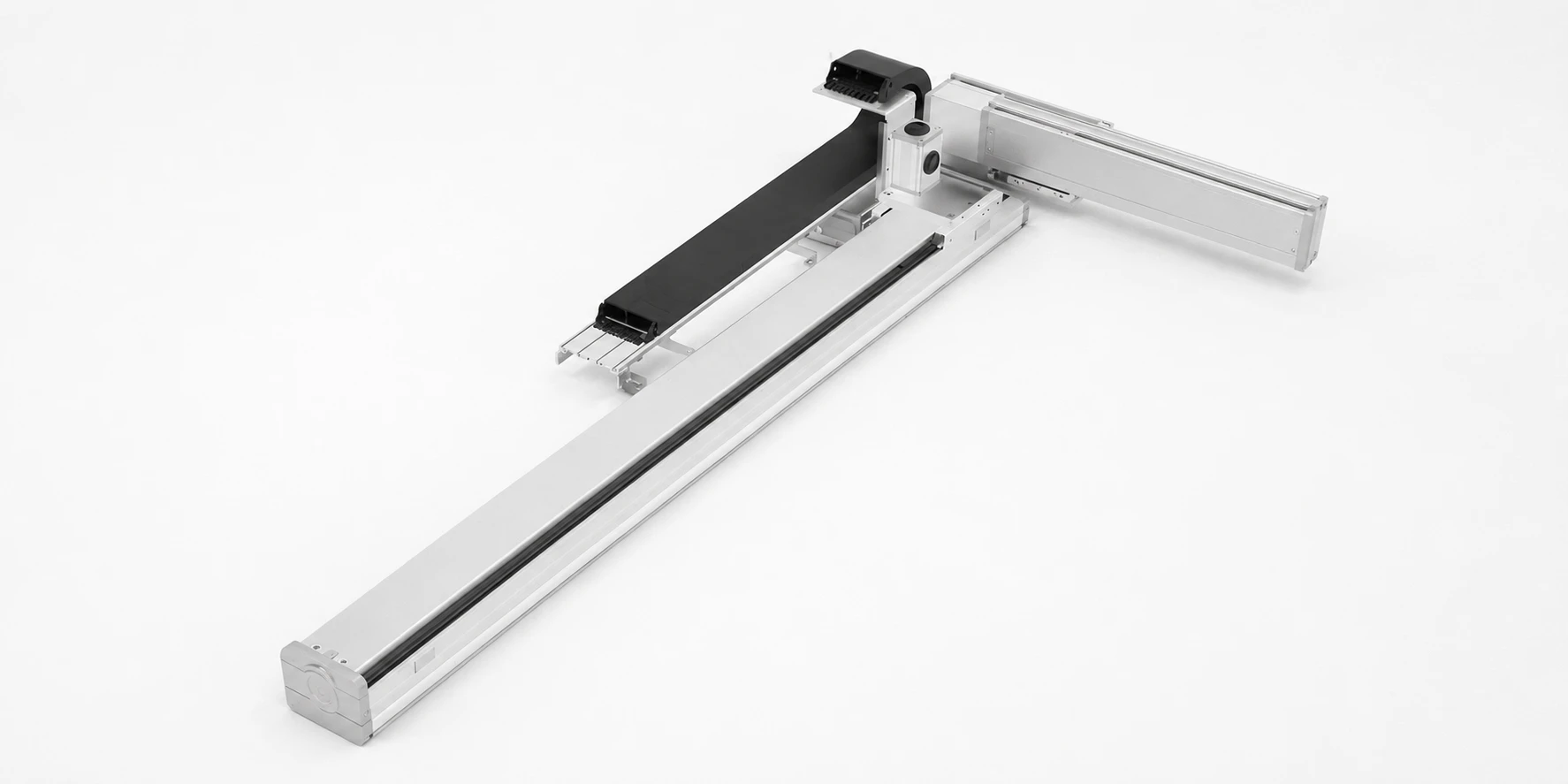
5. Cantilever Cartesian Robot
Structure: An extending axis supported from only one end.
Application: Side-mounted access or suspended part insertion.
Constraint: The extending arm's length must be limited to control deflection and vibration at the tool tip.
Benefit: Provides unhindered access to the work area from the side, ideal for open-frame machine structures.
Key Configuration Parameters
Each multi-axis system can be reviewed against specific mechanical and electrical constraints before quotation.
Stroke and Working Envelope
Longer travel may require additional attention to beam rigidity, guide rail support, and drive selection to prevent sag or resonance.
Payload and Center of Gravity
Vertical axes must account for payload holding, braking, and falling prevention. High acceleration with an eccentric load may increase vibration and settling time.
Drive System and Motor Orientation
Motor installation direction (inline, parallel, or reversed) can be configured to fit the available installation space and avoid interference with machine frames.
Gantry Synchronization
Gantry systems require parallel-axis alignment. Dual servo drives with synchronization capabilities should be confirmed from the customer’s layout drawing.
Environmental and Duty Cycle
Continuous high-speed operation influences cable carrier routing, lubrication intervals, and the choice of protective covers.
Engineering Solutions for Project Constraints
How we address actual procurement and integration challenges on the factory floor.
Multi-Axis Cumulative Error
Why it occurs: Stacking multiple axes amplifies minor base flatness or squareness variations.
Configuration: Machined mounting plates and pinned connection interfaces simplify perpendicularity verification.
Result: Helps control cumulative positioning errors and improves installation consistency.
Payload & Rigidity Mismatch
Why it occurs: High acceleration with an offset payload center of gravity induces structural resonance.
Configuration: Drive system and beam profile sizing are evaluated against the target cycle profile.
Result: Reduces vibration and settling time during dynamic movement.
Standard Dimensions Don't Fit
Why it occurs: The available installation space in the machine layout is heavily restricted.
Configuration: Axis stroke, motor position, and mounting-hole locations can be configured around the customer drawing.
Result: Makes mechanical integration more predictable without redesigning the main frame.
Gantry Synchronization Issues
Why it occurs: Uneven loading or mechanical binding causes the parallel axes to skew.
Configuration: Dual-drive controllers and precise installation datum edges are specified for the base.
Result: Helps maintain parallelism and prevents gantry beam deformation.
Complex Integration
Why it occurs: Sourcing motors, sensors, and cables separately leads to compatibility issues.
Configuration: Systems can be supplied with pre-routed cable carriers, home sensors, and compatible motor flanges.
Result: Simplifies wiring and I/O integration within the control cabinet.
Lack of Commissioning Support
Why it occurs: Insufficient technical documentation delays programming and setup.
Configuration: CAD drawings, wiring diagrams, and basic parameter documentation are prepared based on the approved design.
Result: Clarifies mechanical and electrical interfaces for maintenance access.
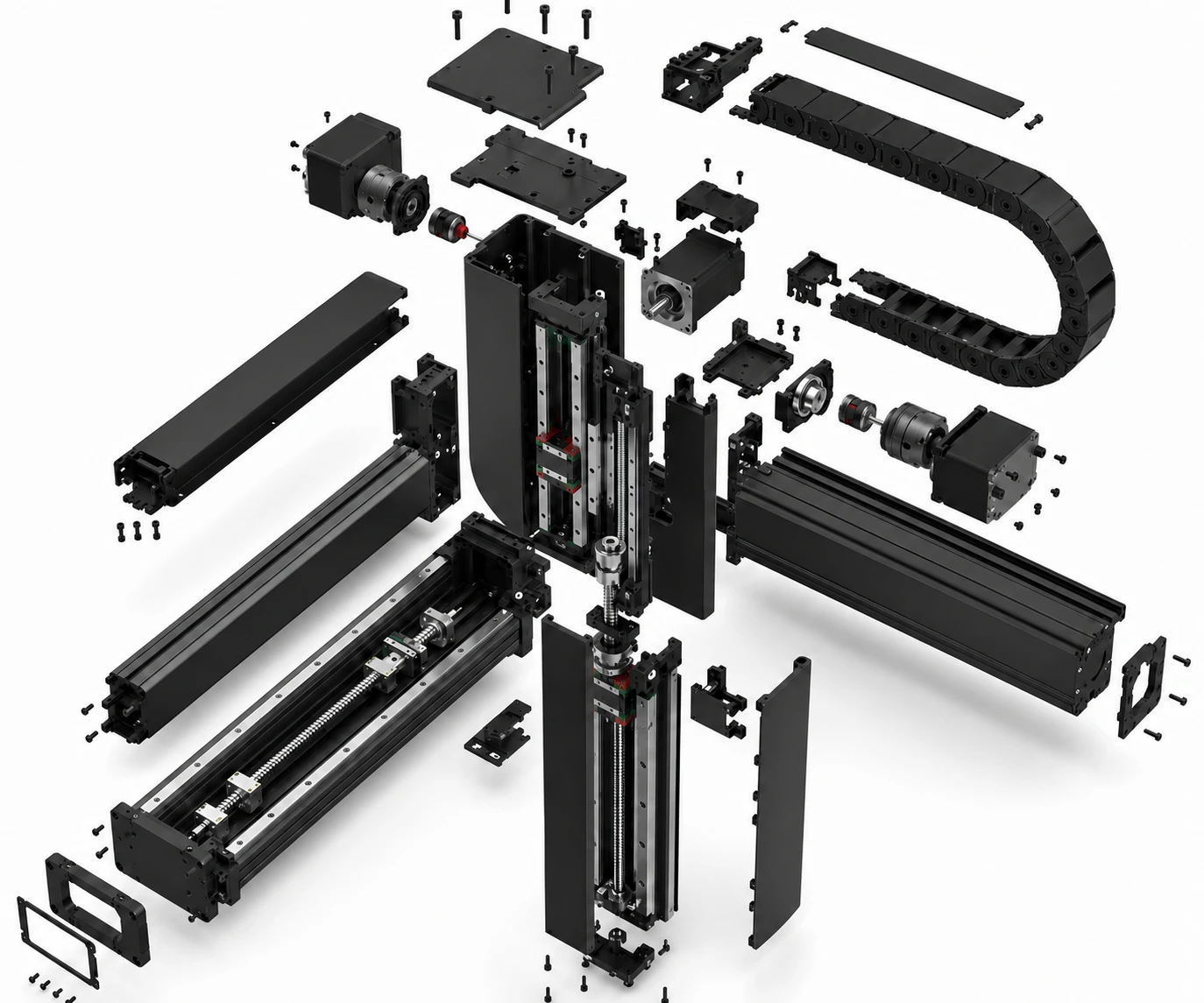
Main Components & Materials
Understanding the internal structure helps clarify maintenance requirements and integration points.
Structural Base or Frame
Aluminum extrusions suit standard positioning tasks, while steel structures may be evaluated for heavy payloads or high-rigidity demands.
Drive System & Linear Guideways
Selection between ball screws, timing belts, or linear motors depends on the required travel, speed, and precision.
Motor and Controller
Servo motors or stepper motors are integrated based on cycle time and fieldbus compatibility requirements.
End-Effector Mounting Plate
Mounting-hole patterns must be confirmed to ensure secure attachment of grippers or process tools.
Cable Carrier & Sensors
Cable routing affects long travel continuous operation. Limit sensors and home switches are used for travel protection and homing.
Linear Axis Drive Comparison
Compare drive options to match your project's positioning and speed requirements.
| Drive Type | Typical Travel | Speed Characteristics | Load Condition | Main Project Constraint |
|---|---|---|---|---|
| Ball Screw Drive | Short to medium | Moderate (limited by critical speed) | High axial thrust capacity | Screw whip limits maximum stroke length. |
| Timing Belt Drive | Medium to long | High transfer speed | Light to moderate | Belt stretch may affect repeatability over long distances. |
| Linear Motor Drive | Short to long | Very high speed and acceleration | Light to moderate | Requires robust thermal management and clean environments. |
| Rack-and-Pinion | Very long | Moderate to high | Heavy payloads | Backlash must be managed for high-precision tasks. |
• Ball screws may suit controlled positioning over moderate travel where higher repeatability is required.
• Belt drives may suit longer travel and higher transfer speed where the required positioning level is appropriate for packaging or handling.
• Linear motors may suit applications requiring direct drive and reduced mechanical transmission for fast cycle times.
• Rack-and-pinion drives may be considered for long travel and larger mechanical structures typically seen in gantry setups.
Industrial Automation Applications
Cartesian automation systems can be adapted to various fixed-path processes.
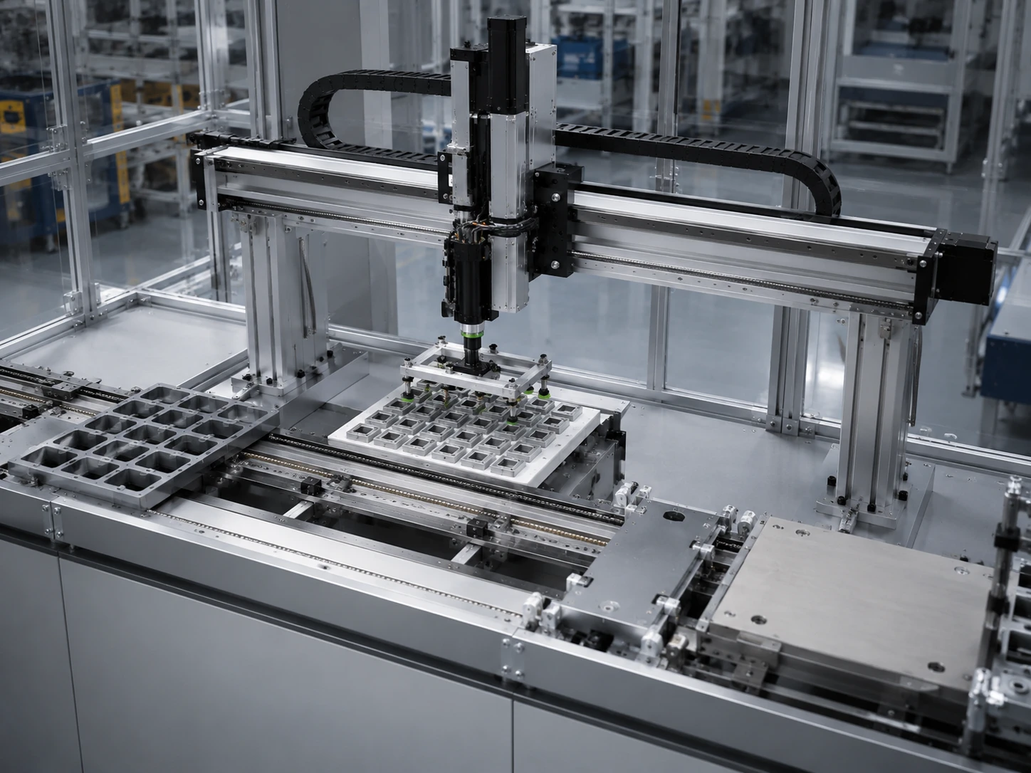
Pick and Place
Process: Transferring workpieces between stations.
Consideration: Z-axis payload and end-effector weight.
Benefit: Predictable cycle times for repetitive handling.
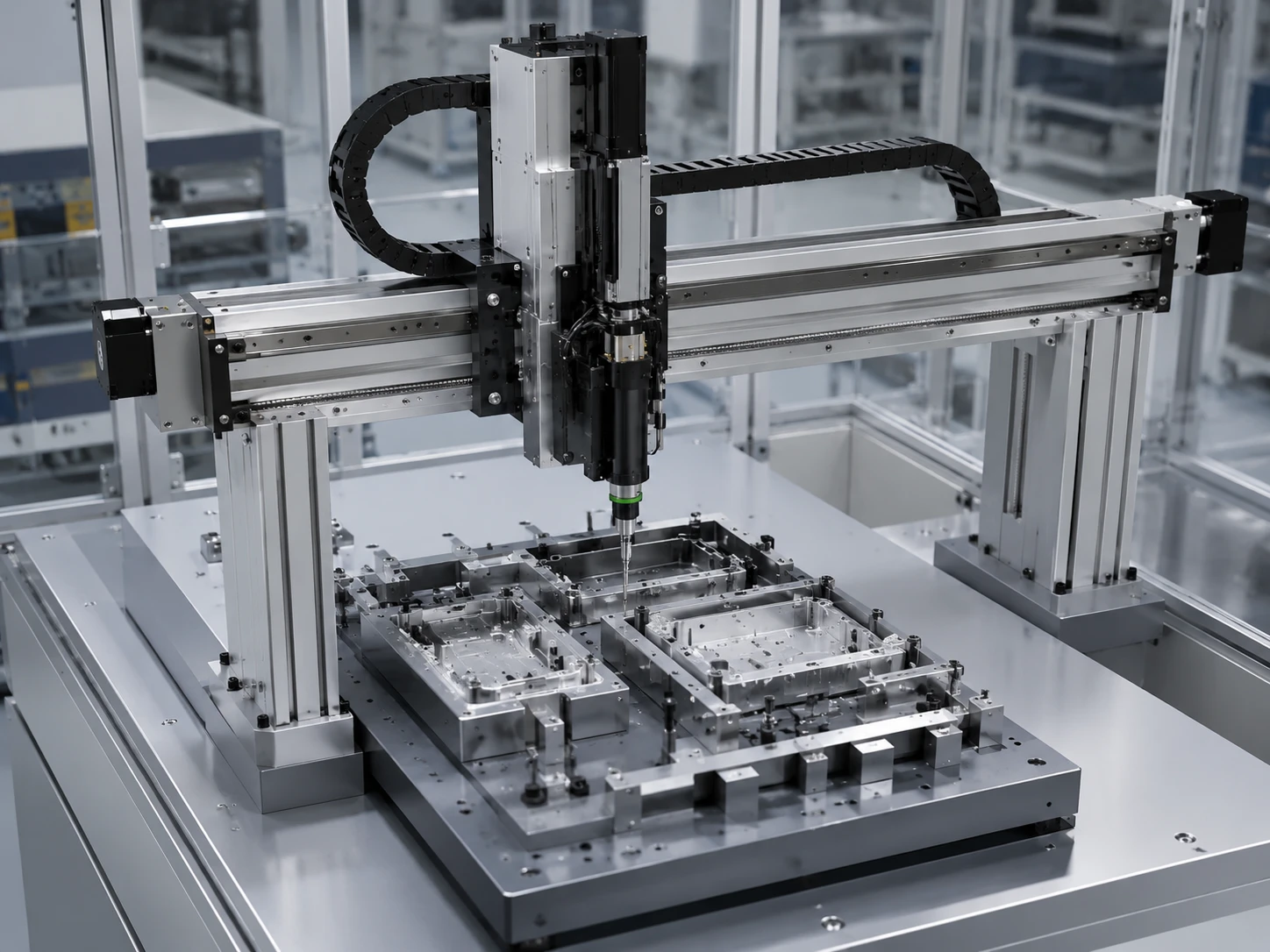
Assembly and Insertion
Process: Pressing or inserting components.
Consideration: Base rigidity and positioning repeatability.
Benefit: Helps control alignment errors during assembly.
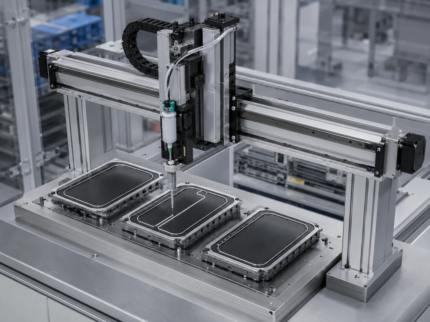
Dispensing and Adhesive
Process: Applying glue or sealant along a path.
Consideration: Continuous path control and controller communication.
Benefit: Ensures consistent application speed and volume.
Machine Loading
Process: Feeding raw materials into CNC machines.
Consideration: Integration with machine door and I/O signals.
Benefit: Reduces manual loading time and improves safety.
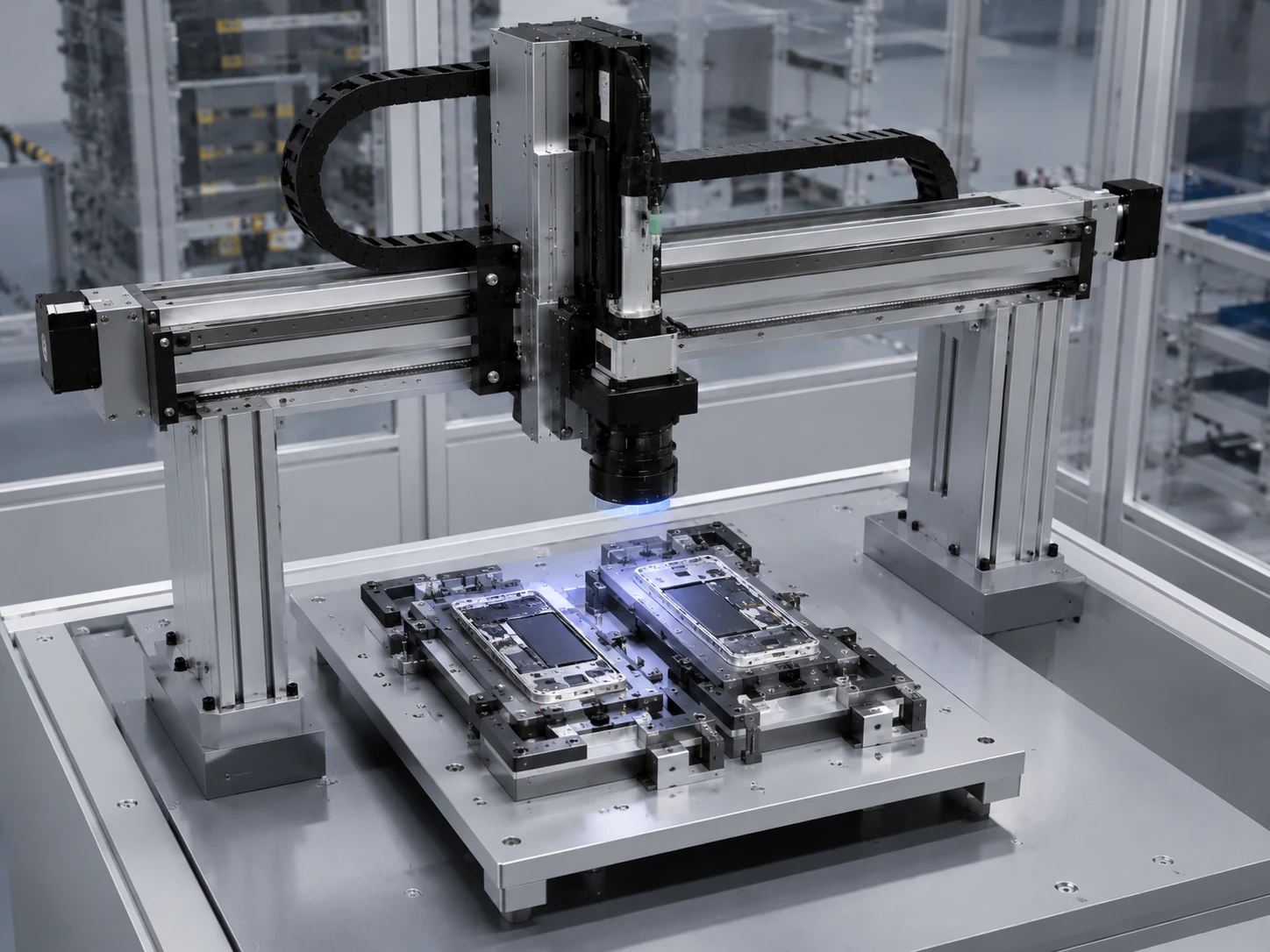
Inspection and Measurement
Process: Moving cameras or sensors over a workpiece.
Consideration: Vibration control and settling time.
Benefit: Provides repeatable scanning paths for quality verification.

Packaging and Palletizing
Process: Stacking boxes or arranging products.
Consideration: Large working envelope and conveyor synchronization.
Benefit: Handles variable product sizes within a wide area.
Which Robot Structure Should You Choose?
Selecting the right kinematics depends heavily on your project constraints:
选择合适的运动学方案很大程度上取决于您的项目限制:
- Required working envelope
- Payload and tool orientation
- Available floor or overhead space
- Cycle requirement
- Programming resources
Cartesian robots usually suit rectangular working envelopes, long strokes, and fixed-path tasks.
SCARA robots typically suit high-speed planar assembly and handling.
Six-axis robots generally suit tasks requiring multi-directional posture changes and complex articulation.
| Feature | Cartesian Robot | SCARA | Six-Axis |
|---|---|---|---|
| Working Envelope | Rectangular / Scalable | Cylindrical / Fixed | Spherical / Fixed |
| Payload Capacity | High (can be distributed) | Low to Moderate | Moderate to High |
| Orientation Flexibility | Low (Fixed axes) | Moderate (Z-axis rotation) | High (Full articulation) |
| Integration Complexity | Moderate (Requires alignment) | Low (Standalone unit) | Moderate (Complex programming) |
| Installation Footprint | Configurable (Overhead possible) | Compact base | Compact base |
How to Select a Cartesian Robot
Follow this workflow before requesting a quotation to ensure accurate configuration.
1. Define the Working Envelope
Determine the required stroke on each axis based on the machine layout drawing and available installation space.
2. Confirm Payload & Center of Gravity
Calculate the total end-effector weight and workpiece mass. Note any offset center of gravity that might induce moment loads.
3. Define Speed & Cycle Requirements
Specify the target cycle time, maximum speed, and acceleration to determine drive and motor sizing.
4. Confirm Positioning Requirements
Review the accuracy or repeatability requirement based on the process (e.g., precision assembly vs. general packaging).
5. Select Axis Structure & Drive
Choose between ball screw, belt, or linear motor, and determine the mounting direction (e.g., XY, Gantry).
6. Confirm Controller & Interfaces
Specify motor preference, fieldbus protocol, I/O requirements, and maintenance space for cabinet compatibility.
Custom Configuration & Integration
Because machine layouts differ, axis combinations, stroke, and motor positions can be configured based on project requirements, subject to engineering evaluation.
Typical Project Workflow
- Requirement Collection: Review payload, speed, and working envelope.
- Drawing Review: Check mounting-hole patterns and cable carrier direction.
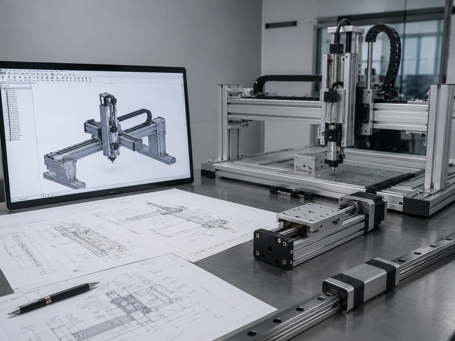
- Configuration Proposal: Submit 2D/3D CAD models for integration check.
- Technical Confirmation: Finalize motor, controller, and sensor arrangement.
- Sample Approval: First-unit verification against the approved drawing.
- Batch Control: Confirmed drawings and interface requirements are retained as the reference for repeat orders.
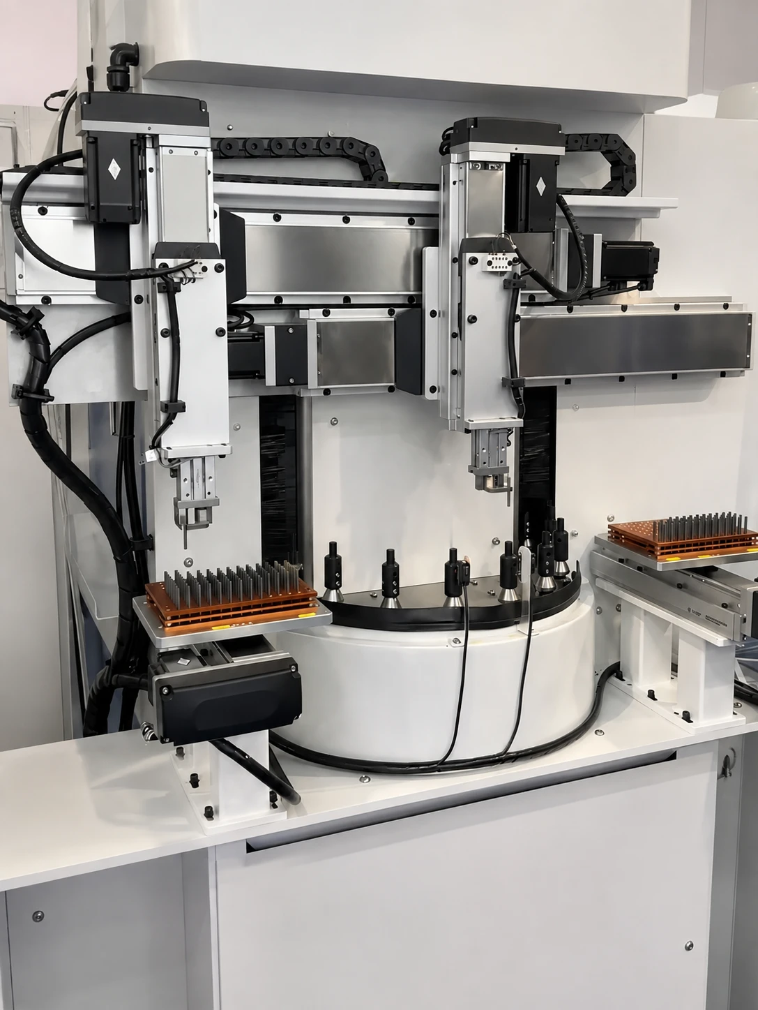
Technical Documentation
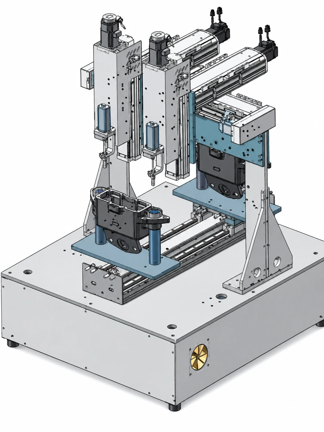
To clarify commissioning and maintenance access, the following materials can be provided based on the final configuration:
- 2D interface drawings
- 3D CAD models
- Basic wiring diagrams
- Motor & Controller manuals
- I/O definition tables
- Spare-parts lists
Quality Verification
Each unit undergoes specific inspection steps to verify the configuration against approved drawings:
- 1 Axis Travel Inspection: Checking smoothness and limit sensor function.
- 2 Mounting Interface Verification: Measuring hole patterns using [Insert Actual Inspection Equipment].
- 3 Multi-Axis Movement Test: Motor rotation and homing check before shipment.
- 4 Configuration Consistency: Comparing the bill of materials and packaging list with the interface record.
Manufacturing & Assembly Capabilities
See how Cartesian robot systems are assembled and reviewed for industrial buyers.
Factory Overview & Assembly Process
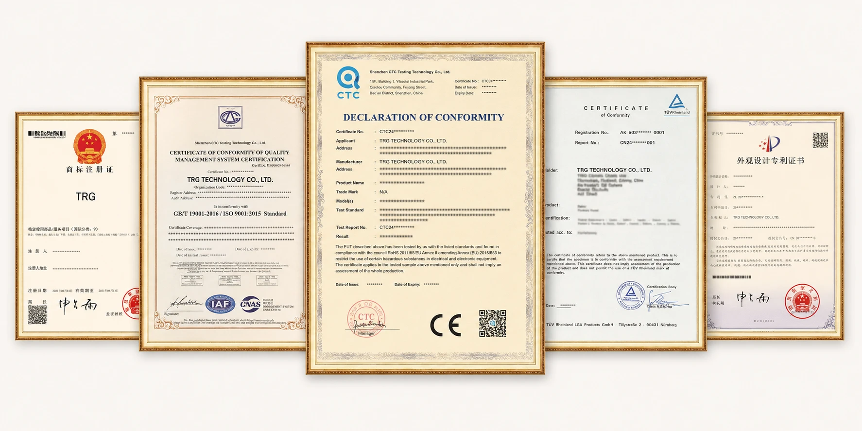
Company Certificates
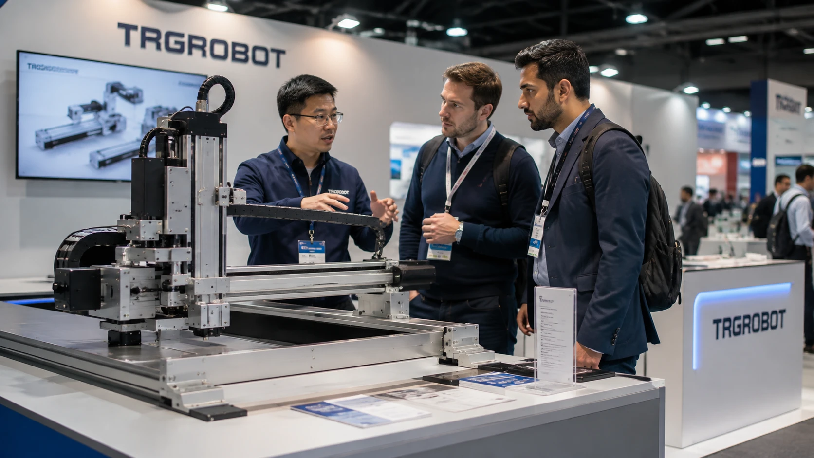
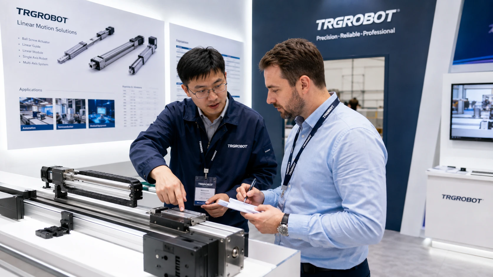
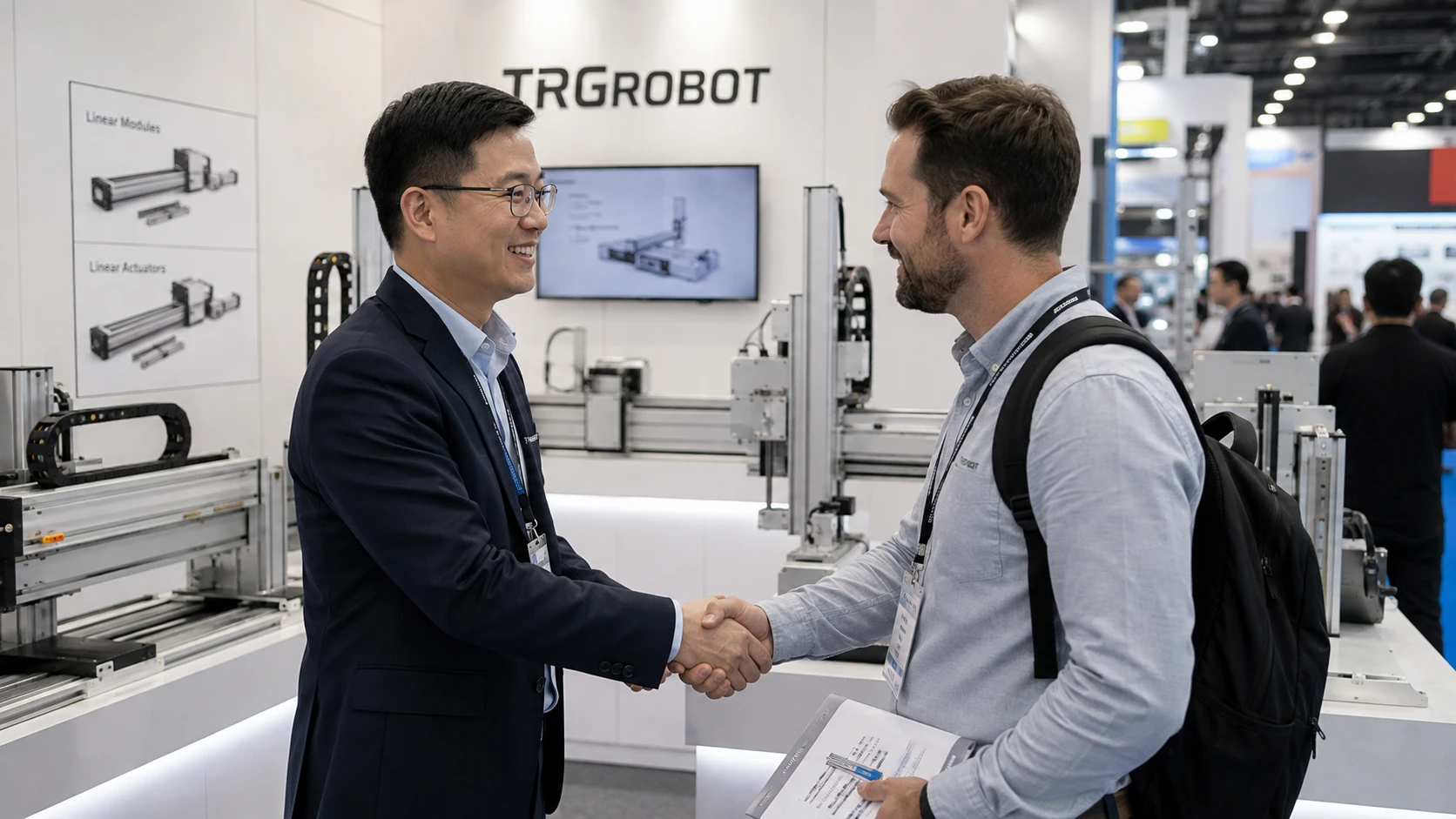
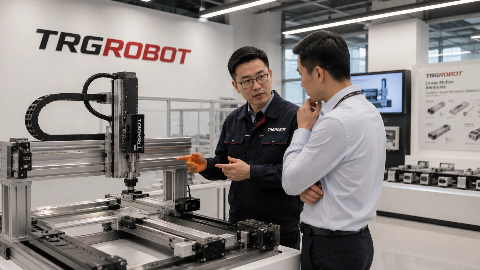
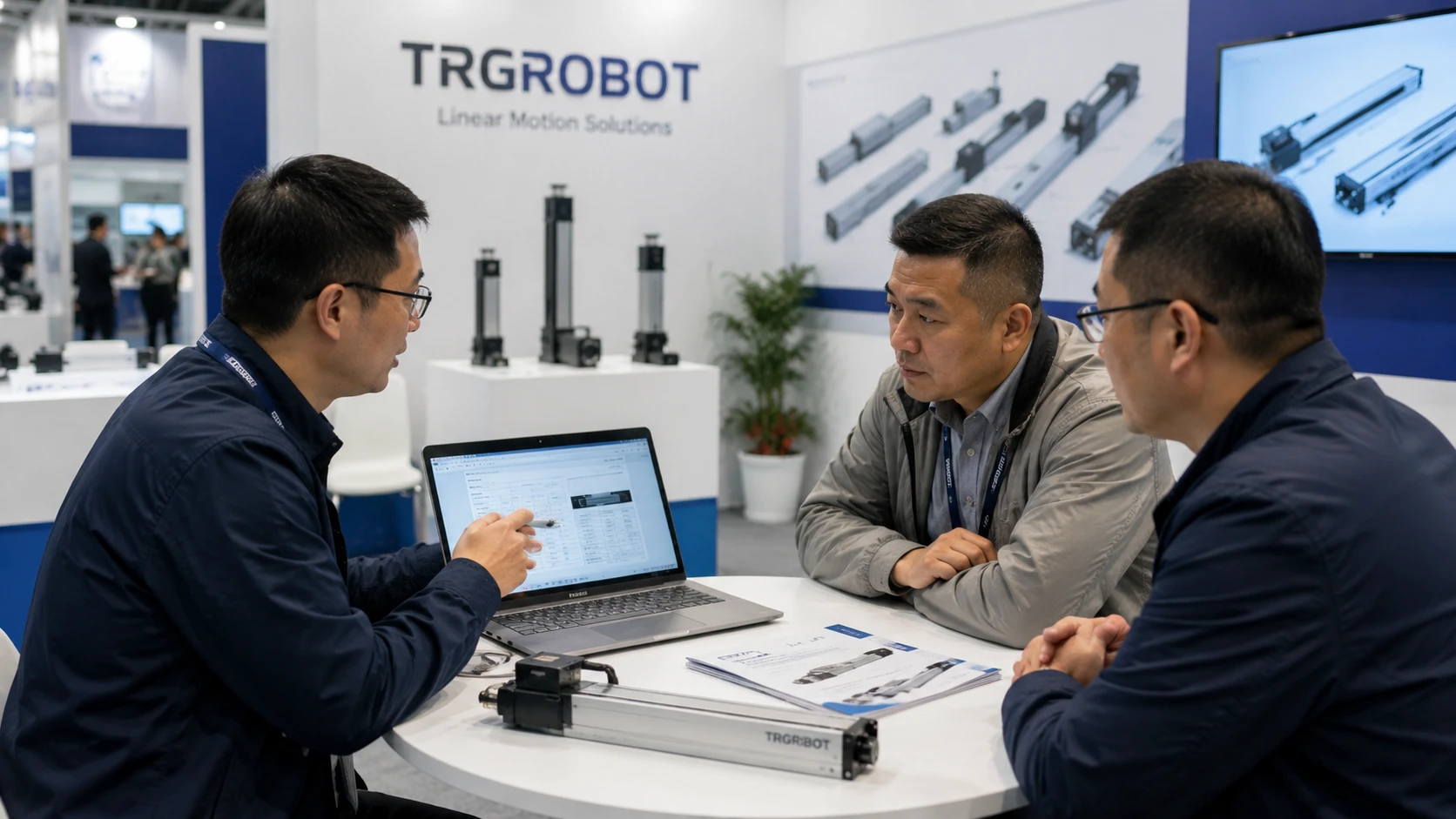
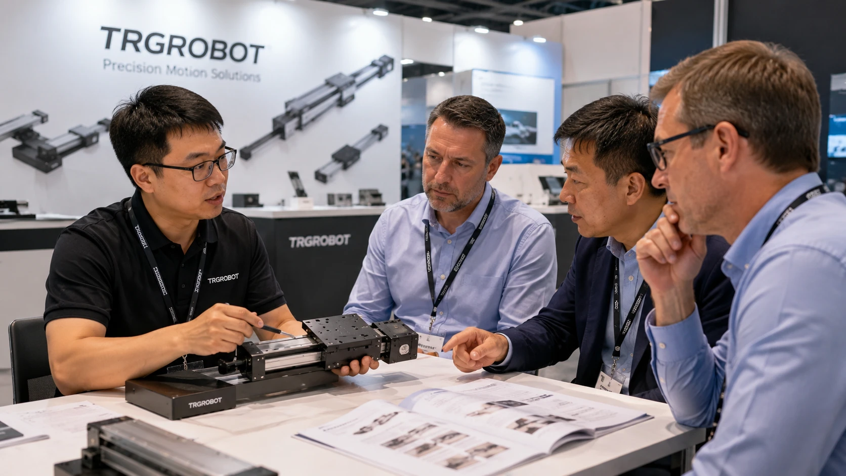
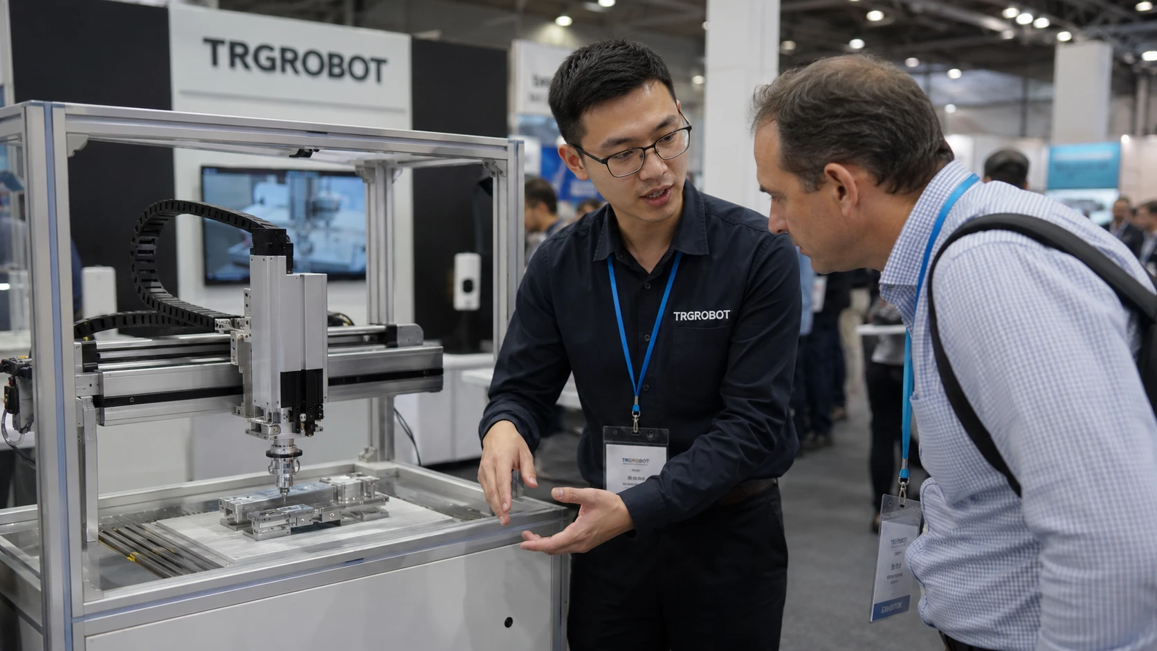
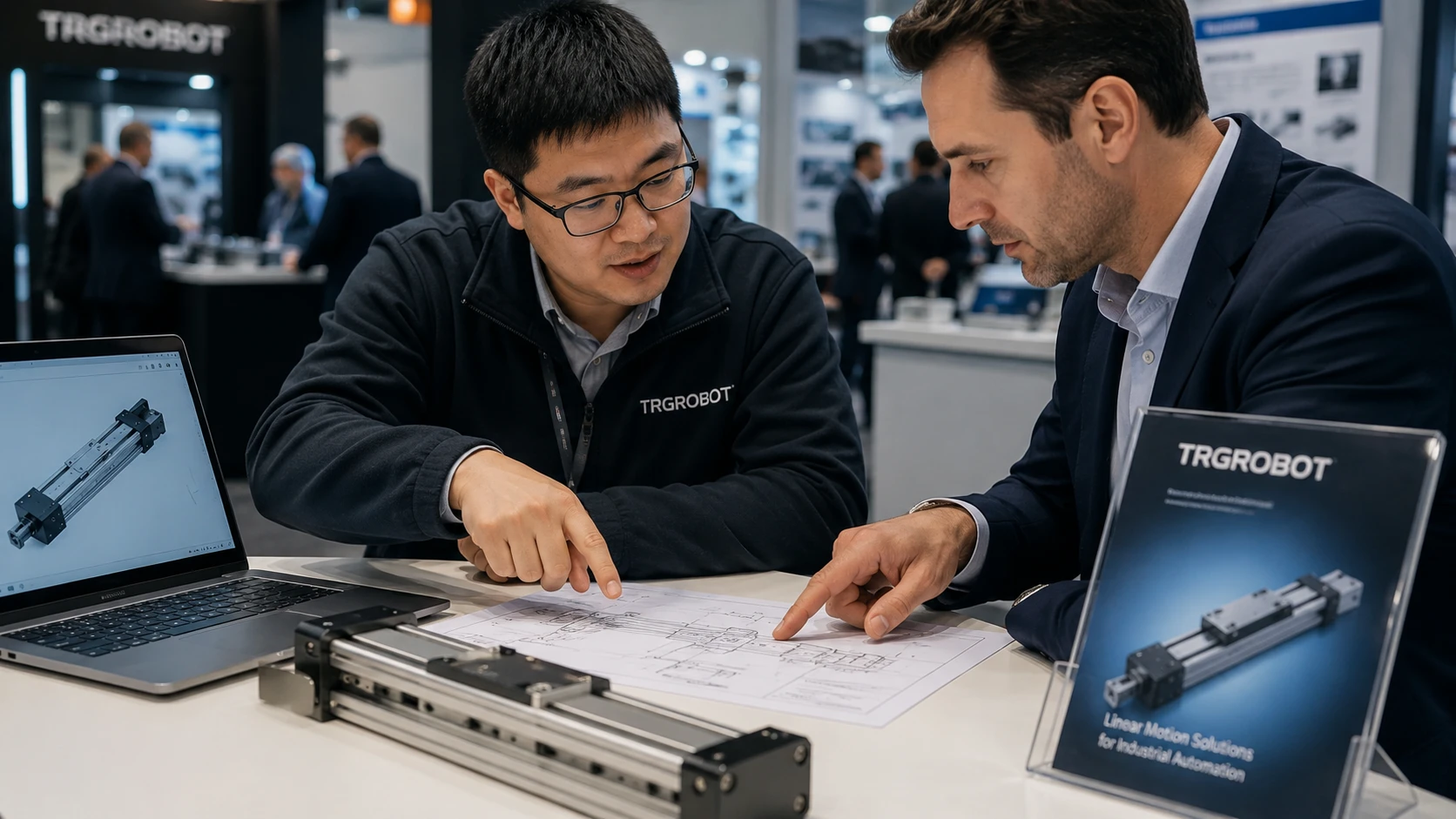
Face-to-Face Technical Communication
Discussing product configuration and collecting application requirements with industrial buyers at offline trade shows.
Typical Project Configuration Examples
Examples of how parameters are matched to specific project constraints.
Example 1: Automated Dispensing System for Electronic Components
- Industry:Electronics Assembly / Precision Manufacturing
- Constraint: Limited machine space, short cycle time, and stable dispensing accuracy required for small electronic parts.
- Axis Configuration: XY Cartesian Robot with Z-Axis Dispensing Head
- Payload & Stroke: 3–5 kg payload / 400–800 mm working stroke
- Proposed Configuration: Compact XY linear module system with a vertical Z-axis actuator, integrated cable carrier, and customized mounting plate for the dispensing valve..
- Result: The system achieved stable point-to-point dispensing, reduced manual alignment time, and allowed the customer to integrate the motion unit into the existing production line without major machine redesign.
Example 2: Gantry Transfer System for Large Workpiece Handling
- Industry: Automotive Parts / Industrial Automation
- Constraint: Large workpieces needed to be transferred across a wide working area while maintaining rigidity and repeatable positioning.
- Axis Configuration:Gantry Cartesian Robot
- Payload & Stroke: 20–50 kg payload / 1500–3000 mm X-axis travel
- Proposed Configuration: Dual-drive gantry structure with synchronized servo motors, reinforced aluminum profiles, precision linear guides, and customized end-effector mounting interface.
- Result: The gantry system improved transfer stability, reduced vibration during high-speed movement, and provided enough working space for loading, positioning, and automated handling operations.
Frequently Asked Questions
Common technical and procurement questions regarding Cartesian automation systems.
What is a Cartesian robot?
What is a Cartesian robot used for?
What is the difference between a Cartesian robot and a gantry robot?
How do I select the correct Cartesian robot?
What information is required for a quotation?
Can the stroke and mounting dimensions be customized?
How does a Cartesian robot compare with a SCARA robot?
Which drive system should be used for a Cartesian robot?
What affects the cost of a Cartesian robot system?
Can motors, controllers and fieldbus interfaces be specified?
What maintenance does a Cartesian robot require?
Can you provide CAD drawings and technical documentation?
Request a Cartesian Robot Configuration Review
Send your machine layout, required travel, payload, and controller preference. The configuration can then be reviewed against the available installation space, axis structure, and interface requirements before quotation.